139 Wyniki
Wyświetl wyniki:
Sortuj według:

Podczas obliczania siły tnącej w programie Wymiarowanie betonu zbrojonego, działającą siłę tnącą Vz można zredukować zgodnie z EN 1992-1-1. Poniższy artykuł opisuje redukcję siły tnącej od obciążeń skupionych w pobliżu podpory oraz wymiarowanie sił tnących w odległości d od krawędzi podpory w przypadku obciążenia równomiernie rozłożonego.

Każdego dnia tysiące inżynierów konstrukcyjnych projektują elementy konstrukcyjne, korzystając z wzorów kontroli projektu, uwzględniających krytyczne obciążenie wyboczeniowe. Ale skąd wzięły się te starożytne wzory, które opracował ponad 200 lat temu i które stanowią podstawę wszystkich trzech koncepcji projektowania konstrukcji stalowych?

W artykule przedstawiono równania wykorzystywane przez program do określenia podpór podporowych na podstawie parametrów słupa.

W tym artykule pokażemy, jak zdefiniować żebra podłużne na blasze pręta za pomocą komponentu „Żebro” w rozszerzeniu Połączenia stalowe.

Zrozumienie sztywności połączeń stalowych ma kluczowe znaczenie w projektowaniu konstrukcji. Często połączenia są traktowane jako połączenia całkowicie sztywne lub przegubowe, co może prowadzić do nieekonomicznych lub nawet ryzykownych warunków projektowych. Dowiedz się, w jaki sposób program RFEM firmy Dlubal i rozszerzenie Połączenia stalowe pomagają weryfikować sztywność połączeń i nośność na zginanie, zapewniając bezpieczniejsze i bardziej ekonomiczne warunki projektowe.
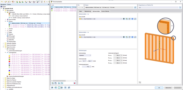
Obliczanie ściany drewnianej zbudowanej z paneli za pomocą grubości typu Drewniany panel szkieletowy
W tym artykule porównano obliczenia drewnianej ściany z paneli za pomocą grubości typu "Drewniany panel szkieletowy" z obliczeniami ręcznymi.

W rozszerzeniu Projektowanie konstrukcji stalowych dla programu RFEM 6 dostępne są trzy typy ram sprężystych (zwykłe, pośrednie i specjalne). Wyniki obliczeń sejsmicznych zgodnie z AISC 341-22 są podzielone na dwie sekcje: wymagania dotyczące prętów i połączeń.
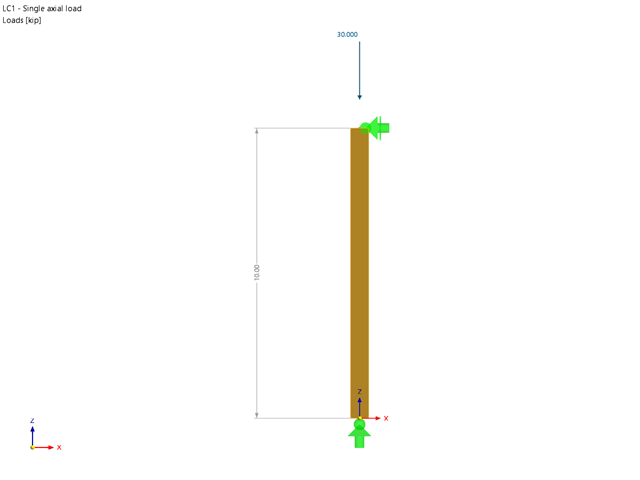
Rozszerzenie Wymiarowanie drewna umożliwia wymiarowanie słupów drewnianych zgodnie ze standardową metodą ASD 2018 NDS. Dokładne wyznaczenie nośności na ściskanie oraz współczynników redukcyjnych dla prętów drewnianych jest konieczne dla bezpieczeństwa konstrukcji. Poniższy artykuł weryfikuje maksymalną wytrzymałość na wyboczenie krytyczną obliczoną w module rozszerzeniowym Wymiarowanie drewna przy użyciu równań analitycznych krok po kroku zgodnie z normą NDS 2018, w tym współczynników dostosowania przy ściskaniu, skorygowanej wartości obliczeniowej na ściskanie i końcowego stopnia wyboczenia.

W tym artykule wyjaśniono, jak działają obliczenia podczas wstępnej analizy sztywności w programie Połączenia stalowe.

W rozszerzeniu Projektowanie konstrukcji stalowych dla programu RFEM 6 dostępne są trzy typy ram sprężystych (zwykłe, pośrednie i specjalne). Wyniki obliczeń sejsmicznych zgodnie z AISC 341-16 są podzielone na dwie sekcje: wymagania dotyczące prętów i połączeń.

Obliczanie ramy momentowej zgodnie z AISC 341-16 jest teraz możliwe w rozszerzeniu Projektowanie konstrukcji stalowych dla programu RFEM 6. Wynik obliczeń sejsmicznych jest podzielony na dwie sekcje: wymagania dotyczące prętów i połączeń. W tym artykule omówiono wymaganą wytrzymałość połączenia. Przedstawiono przykładowe porównanie wyników pomiędzy RFEM a AISC Seismic Design Manual.
Wydarzenia ostatnich lat przypominają nam o znaczeniu konstrukcji odpornych na trzęsienia ziemi w zagrożonych regionach. Projektowanie konstrukcji na obszarach narażonych na trzęsienia ziemi jest ciągłym kompromisem między efektywnością ekonomiczną i możliwościami finansowymi, a także bezpieczeństwem. Jeżeli zawalenie jest nieuniknione, należy ocenić, w jaki sposób wpłynie ono na konstrukcję. Celem tego artykułu jest przedstawienie jednej z opcji przeprowadzenia tej oceny.
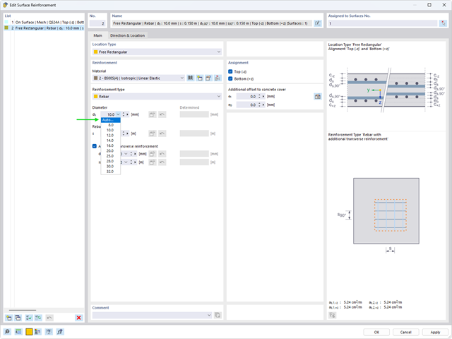
Automatyczny proces wymiarowania zbrojenia określa zbrojenie powierzchniowe, które zapewnia wymaganą ilość zbrojenia wynikającego z obliczeń.
W wielu konstrukcjach szkieletowych zastosowanie prostego pręta nie jest już wystarczające. Często należy wziąć pod uwagę osłabienia przekroju lub otwory w belkach betonowych. Dla takich zastosowań dostępny jest typ pręta "Model powierzchniowy". Można go można zintegrować z modelem jak w przypadku każdego innego pręta i oferuje on wszystkie opcje modelu powierzchniowego. Ten artykuł techniczny pokazuje zastosowanie pręta typu Model powierzchniowy w istniejącym układzie konstrukcyjnym i opisuje integrację otworów pręta.
Modalny współczynnik istotności jest wynikiem analizy stateczności liniowej i opisuje jakościowo stopień udziału poszczególnych prętów w określonym kształcie drgań.
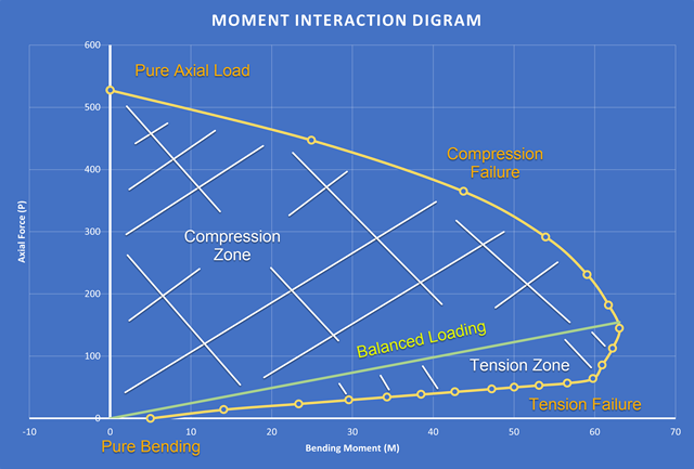
Nowością w programie RFEM 6 podczas wymiarowania słupów betonowych jest możliwość generowania wykresu interakcji momentów zgodnie z ACI 318-19 [1]. Podczas wymiarowania prętów żelbetowych istotnym narzędziem jest wykres interakcji momentów. Wykres interakcji momentów przedstawia zależność między momentem zginającym a siłą osiową w dowolnym punkcie zbrojenia. Cenne informacje, takie jak wytrzymałość i zachowanie betonu w różnych warunkach obciążenia, wyświetlane są wizualnie.

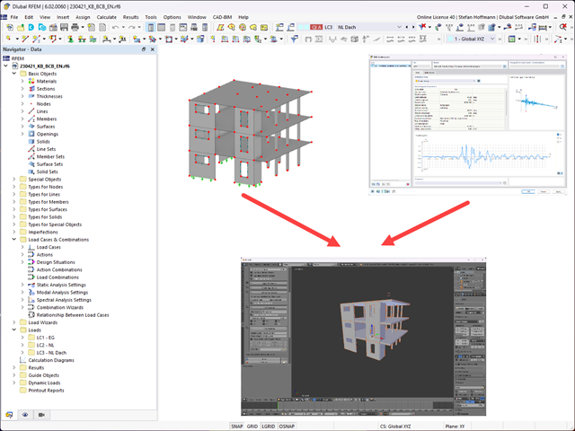
Niniejszy artykuł jest związany z trwającym projektem, w ramach którego opracowywany i wdrażany jest cyfrowy bliźniak konstrukcyjny mostu Kalix w Szwecji.
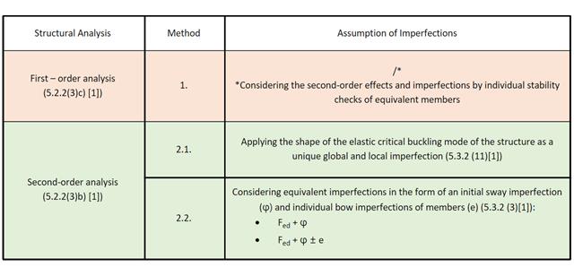
W tym artykule w Bazie informacji omówiono różne metody analizy stateczności opisane w normie EN 1993-1-1:2005 i ich zastosowanie w programie RFEM 6.
W tym artykule przedstawimy Państwu "Dostosowanie wyników powierzchni" w RFEM 6, odpowiadające funkcji "Obszar uśredniania" zaimplementowanej w RFEM 5.
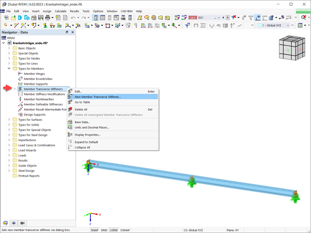
W tym artykule pokazano, jak definiować różne typy usztywnień poprzecznych pręta w programie RFEM 6 i RSTAB 9. Pokazano tu również, w jaki sposób uwzględnić je w projektowaniu i obliczeniach prętów o 7 stopniach swobody.
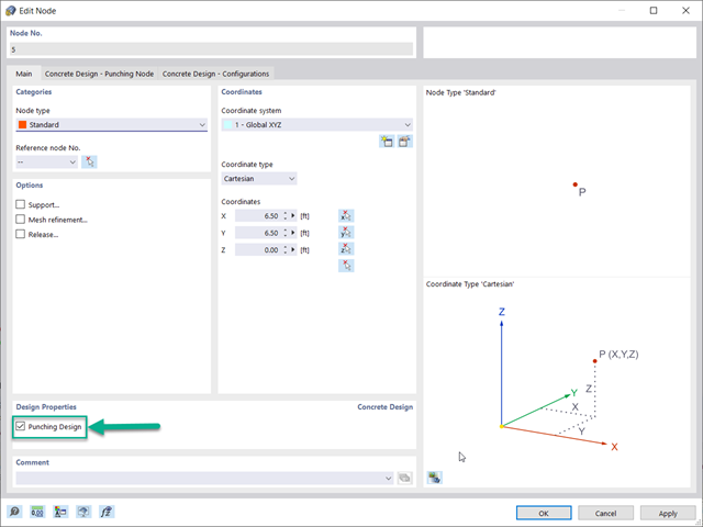
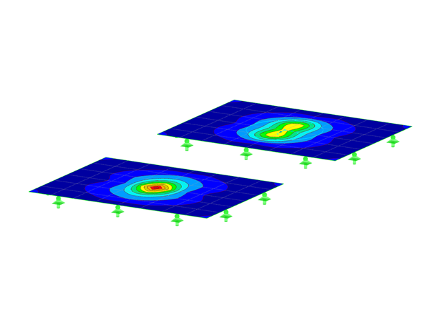
Optymalnym scenariuszem, w którym należy zastosować obliczenia wytrzymałości na przebicie, zgodnie z ACI 318-19 lub CSA A23.3:19, jest sytuacja, w której w płycie występuje duża koncentracja obciążeń lub sił reakcji występujących w jednym węźle. W programie RFEM 6 węzeł, w którym występuje przebicie, nazywany jest węzłem z przebiciem. Przyczyny tak dużej koncentracji sił mogą być spowodowane przez słup, siłę skupioną lub podporę węzłową. Łączenie ścian może również powodować obciążenia skupione na końcach, narożach i na końcach obciążeń liniowych i podpór.
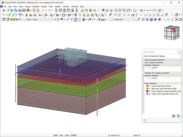
W tym artykule omówiono wyniki analizy geotechnicznej oraz ich graficzne i tabelaryczne przedstawienie w programie RFEM 6.

Analiza dynamiczna w RFEM 6 i RSTAB 9 jest podzielona na kilka rozszerzeń. Rozszerzenie Analiza modalna jest niezbędne dla wszystkich innych rozszerzeń do analizy dynamicznej, ponieważ przeprowadza analizę drgań własnych dla modeli prętów, powierzchni i brył.

Rozszerzenie Wymiarowanie betonu umożliwia wymiarowanie słupów betonowych zgodnie z ACI 318-19. Poniższy artykuł potwierdzi wymiarowanie zbrojenia w rozszerzeniu Wymiarowanie betonu przy użyciu równań analitycznych krok po kroku zgodnie z normą ACI 318-19, w tym wymagane zbrojenie podłużne, pole przekroju brutto i rozmiar/rozstaw ściągu.
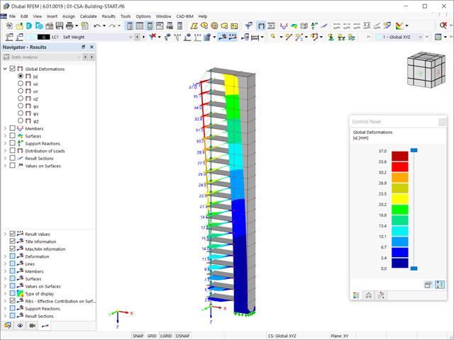
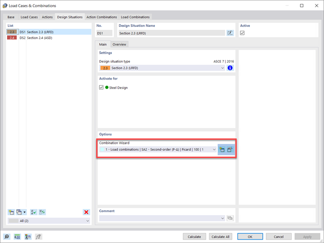
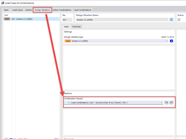
Rozszerzenie Analiza etapów budowy (CSA) umożliwia wymiarowanie konstrukcji prętowych, powierzchniowych i bryłowych w programie RFEM 6 z uwzględnieniem określonych etapów budowy związanych z procesem konstrukcyjnym. Jest to o tyle istotne, że budynki nie powstają w całości od razu, lecz poprzez stopniowe łączenie poszczególnych części konstrukcyjnych. Poszczególne kroki, w których elementy konstrukcyjne oraz obciążenia są dodawane do budynku, nazywane są etapami budowy, podczas gdy sam proces budowy nazywa się procesem konstrukcyjnym.
Norma dotycząca konstrukcji stalowych AISC 360-16 wymaga uwzględnienia stateczności konstrukcji jako całości oraz każdego z jej elementów. Dostępne są różne metody, w tym metoda bezpośredniego uwzględnienia w analizie, metoda długości efektywnej i metoda analizy bezpośredniej. W tym artykule podkreślono ważne wymagania rozdz. C oraz metodę bezpośredniej analizy, która zostanie uwzględniona w modelu konstrukcji stalowej wraz z zastosowaniem w programie RFEM 6.
Zgodnie z rozdz. 6.6.3.1.1 i 10.14.1.2 ACI 318-19 i CSA A23.3-19, program RFEM efektywnie uwzględnia redukcję sztywności prętów betonowych i powierzchni dla różnych typów elementów. Dostępne typy wyboru obejmują zarysowane i niezarysowane ściany, płaskie płyty, belki i słupy. Dostępne w programie mnożniki zaczerpnięto bezpośrednio z tabel 6.6.3.1.1(a) i 10.14.1.2.
Obliczenia na przebicie zgodnie z EN 1992-1-1 należy przeprowadzić dla płyt poddanych obciążeniu skupionemu lub reakcji. Węzeł, w którym przeprowadzana jest analiza nośności na przebicie (tj. w miejscu, w którym występuje problem z przebiciem) nazywany jest węzłem odporności na przebicie. Obciążenie skupione w tych węzłach może zostać wprowadzone przez słupy, siłę skupioną lub podpory węzłowe. Koniec przyłożenia obciążenia liniowego na płyty również jest traktowany jako obciążenie skupione, dlatego należy również kontrolować nośność na ścinanie na końcach, narożach i końcach ścian oraz na końcach lub narożach obciążeń liniowych i podpór liniowych.

Sprawdzenie stateczności dla wymiarowania prętów zastępczych zgodnie z EN 1993-1-1, AISC 360, CSA S16 i innymi normami międzynarodowymi wymaga uwzględnienia długości obliczeniowej (tj. efektywnej długości prętów). W programie RFEM 6 długość efektywną można określić ręcznie, przypisując podpory węzłowe i współczynniki długości efektywnej lub, z drugiej strony, poprzez import z analizy stateczności. Obie opcje zostaną przedstawione w tym artykule poprzez określenie efektywnej długości słupa obramowanego na rysunku 1.

W tym artykule opisano, w jaki sposób płaska płyta budynku mieszkalnego jest modelowana w programie RFEM 6 i wymiarowana zgodnie z Eurokodem 2. Płyta ma grubość 24 cm i jest podparta na słupach o długości 45/45/300 cm w rozstawie co 6,75 m (rysunek 1). Słupy są modelowane jako sprężyste podpory węzłowe poprzez zdefiniowanie sztywności sprężystej na podstawie warunków brzegowych (rysunek 2). Jako materiały wybrano beton C35/45 i stal zbrojeniową B 500 S (A).